WORKING DRAFT — NOT FOR RELEASE
Mobile Solar
SRX-6 Solar Generator
Model SRX-6
Technical Manual
Mobile Solar, Inc.6925 Sycamore Road, Suite B · Atascadero, CA 93422
www.mobilesolarpower.net · 805-466-1006
About Mobile Solar. Mobile Solar designs and manufactures trailer-based solar generator systems in the United States. [Company description to be approved by Travis]1
Applicability. This manual applies to the Mobile Solar SRX-6 solar generator, model configuration SRX-6.
This manual provides the specifications, description, operation, maintenance, and service information for the Mobile Solar SRX-6 solar generator. It is written for the owner and for the qualified personnel who operate, maintain, integrate, or service the unit over its service life.
The SRX-6 produces 120-volt AC power and operates at DC battery and photovoltaic voltages that can cause injury. Installation, service, and any work on energized components should be performed only by personnel qualified to work on AC and DC electrical systems and in accordance with all applicable local and national codes. Read this manual, and in particular Section 2, before operating or servicing the unit.
The following notices appear throughout this manual wherever they apply.
| Notice | Meaning |
|---|---|
| WARNING | A hazard that could cause serious injury or death. |
| CAUTION | A hazard that may cause damage to equipment. |
| IMPORTANT | Information important to correct operation or maintenance; ignoring it may void the warranty. |
| NOTE | Useful supplementary information. |
Every solar generator carries inherent hazards. This section identifies them and the practices that avoid or reduce them. The notices defined in Section 1.2 reappear in the operation and maintenance sections wherever a specific hazard applies.
The SRX-6 delivers 120 VAC and operates internally at a nominal battery voltage of 51.2 VDC (48 V class), with photovoltaic input reaching higher DC voltages. These can cause shock, burns, or arc flash.
The SRX-6 uses self-heated lithium iron phosphate (LiFePO4) batteries. Unlike flooded lead-acid, they do not vent hydrogen, contain no free acid, and require no watering or equalization.
The optional Honda EU3000iS runs on gasoline and produces carbon monoxide.
The SRX-6 is a trailer-mounted solar generator that produces 120-volt AC power from a photovoltaic array and a lithium iron phosphate battery bank, with an optional gasoline generator for extended low-sun operation. It is the smallest unit in the SRX Series and the only one built on a single-axle 3,500 lb GVWR platform.
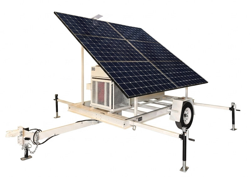
Six major assemblies make up the unit: a fixed-pitch solar array mounted above the chassis; a battery bank in a welded steel frame; the electrical interface holding the inverter, charge controller, system controller, and AC and DC breakers behind a lockable door; an optional generator in a lockable cage on a drop-down service platform; the trailer platform carrying all of it, with four 36-inch outriggers and swing-down jacks for leveling; and remote monitoring hardware reporting status and position over a standard Starlink Mini link.
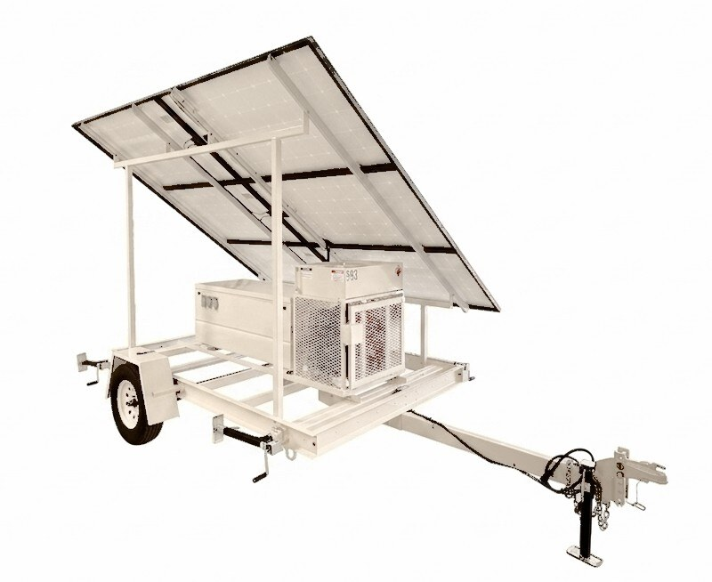
The array has no moving parts and no seasonal adjustment, a deliberate difference from the MS Series. Output is optimized for North American latitudes at a fixed pitch. Exact pitch angle pending confirmation.5 The system runs unattended: the generator, when fitted, starts and stops on battery voltage without operator action, and the monitoring link reports status without a site visit.
| Rated power | 3.6 kW |
| Instantaneous power | 6 kW |
| Output | 120 VAC, 60 Hz, single phase |
| Energy storage | 20.48 kWh LiFePO4 (400 Ah at 51.2 VDC) |
| Solar array | 2,250 W (6 × 375 W) |
| Optional generator | Honda EU3000iS |
| GVWR | 3,500 lb |
| Curb weight | ~2,520 lb |
The electrical interface holds the components that convert and control power, behind a lockable door.
Six 375-watt LG Neon monocrystalline panels, 2,250 watts total, fixed and non-adjustable, optimized for North American latitudes. No moving parts and no seasonal adjustment. Maximum harvest 15 kWh per day; average sunny day 12 kWh per day; both seasonal and site-dependent. An optional auxiliary solar input accepts up to 5 kW of additional array. Panel warranty 25 years limited.
20.48 kWh of self-heated lithium iron phosphate (400 Ah at 51.2 VDC nominal), manufactured by New Use Energy. Usable capacity 100%. Operating range −40 °C to +60 °C, self-heated. Cycle life 6,000 at 80% depth of discharge and 4,000 at 100%. Certified to UN 38.3 and conforming to UL 1642 at the cell level. Battery warranty 5 years.
The bank sits in a welded steel frame (the 6/9/12/15 shared frame measures 45.5 × 19.5 in outside, 42.5 in inside, in 1.5 × 1.5 × 0.125 in hot-rolled angle).
Single-axle platform, nominally 6 ft by 10 ft, 3,500 lb GVWR, roughly 2,520 lb curb weight, built by Mobile Solar. Towing dimensions 8 ft 6 in wide by 14 ft 5 in long by 9 ft high. Four 36-inch outriggers with swing-down jacks and two pin positions. Adjustable-height ball coupler or pintle hitch. Telescopic, removable tongue. Trailer warranty 5 years.
Optional Honda EU3000iS gasoline inverter generator in a lockable cage on a drop-down service platform. 3 kW peak, 2.8 kW rated at 80% load. Sound level 49–58 dB. Onboard fuel 3.4 gal, auxiliary tank 25 gal, 28.4 gal total. Starts and stops automatically on battery voltage (Section 5.4). Generator warranty 3 years.
The SRX-6 ships with cloud-connected remote monitoring and GPS via a Starlink Mini (standard). The Outback Mate3S provides the local display, and the system is OPTICS RE compatible for cloud monitoring and control. Status and position report without a site visit.
Couple to a half-ton or larger tow vehicle. Attach and cross the safety chains under the tongue, connect the breakaway cable, adjust the tow vehicle's brake controller, and connect and check the trailer lights before moving.
Park on level ground with good sun exposure and clearance around the array and generator compartment. Chock the wheels.
Work one corner at a time, before powering on:
Done right, the unit sits level with a slight lift off the tires and all four jacks touching ground.
Outriggers must be deployed and the unit leveled first.
Done right, the Mate3S shows "Inv On" with AC out ~120 V, battery voltage stable (50.4–56 V), and no error codes or warning LEDs.
The unit provides two 20 A NEMA 5-20R straight-blade receptacles and one 30 A NEMA L5-30R twist-lock, all 120 V.7 Each circuit is individually breaker-protected. Total continuous output is 29 A at 120 V (about 3,500 W) across all circuits combined, with a 50 A instantaneous surge for motor starting.
Optional 12 V, 24 V, and 48 V DC outputs are available. What ships on a standard SRX-6, and the terminal locations, pending confirmation.8
The optional Honda EU3000iS starts and stops automatically on battery voltage; the auto-start threshold is 50.4 V.9 Leave the engine switch ON, the choke in, and the fuel valve open (vertical) at all times; everything else is automatic. Turning the key off or running the tank dry stops auto-start and the system will fail to recharge.
The Mate3S home screen shows battery volts, charge/discharge rate, solar input, and inverter mode. Normal operating ranges:
| Battery voltage | 50.4–56 V (generator auto-starts at 50.4 V) |
| AC output | 118–124 V |
| Frequency | 60 Hz |
The Starlink modem's indicator LEDs show the monitoring link; solid green is connected.
Reverse the power-up sequence: set the inverter off, then the AC breakers, then the DC breakers. The full owner-level power-down sequence, including whether the charge-controller breaker is ever switched off, is pending confirmation.10
Unplug all loads. Leave the inverter and all breakers ON so the unit stays powered and reports remotely during transport. Close and lock the box, crank the jacks up, swing the arms in and re-pin, secure the generator cage, extend the tongue, couple to the ball, cross the safety chains, attach the breakaway cable, adjust the brake controller, and connect and check the trailer lights.
Keep the array reasonably clean. Inspect panels and mounting for damage after severe weather.
The LiFePO4 bank is effectively maintenance-free. Any periodic BMS check, firmware update, or self-heat confirmation is pending guidance.11
Follow the Honda EU3000iS schedule for oil, air filter, and spark plug. Use fuel stabilizer for storage.
Check tire pressure and condition, wheel bearings, lights, and jack operation. Verify torque on the critical connections listed in Appendix C.
Protect the array and secure the unit ahead of high winds and storms. Detailed procedure to be adapted from MS-era guidance.12
| Symptom | Check |
|---|---|
| No AC output at outlets | Inverter mode on the Mate3S must show ON. Then check that all breakers are on; if one tripped, reduce load before resetting. |
| Inverter shuts down | Overcurrent (load too high) or low battery (below ~50 V). Reduce load, let the generator recharge if fitted, then restart the inverter via the Mate3S. |
| Battery draining fast | Total load exceeds solar input. Reduce load; check generator fuel if it auto-starts; confirm all breakers on. |
| Generator won't start, or starts then quits | Fuel valve must be open (vertical) and fuel present. If it starts then quits after ~10 s, suspect low oil. Engine key must be ON. |
All values at 25 °C unless stated. Specifications are subject to change; the unit as delivered governs.
| Rated power | 3.6 kW |
| Instantaneous power | 6 kW |
| Output voltage | 120 VAC, 60 Hz, single phase |
| Rated current | 29.2 A |
| Instantaneous current | 50 A |
| Waveform | Pure sine |
| Inverter | Outback Power FXR |
| Inverter warranty | 5 years |
| Chemistry | Lithium iron phosphate (LiFePO4), self-heated |
| Nominal voltage | 51.2 VDC (48 V class) |
| Energy capacity | 20.48 kWh |
| Amp-hour capacity | 400 Ah at 51.2 VDC |
| Usable capacity | 100% |
| Cycle life | 6,000 at 80% DoD; 4,000 at 100% DoD |
| Operating temperature | −40 °C to +60 °C, self-heated |
| Manufacturer | New Use Energy |
| Certification | UN 38.3; UL 1642 at cell level; CE at cell level |
| Battery warranty | 5 years |
| Panels | 6 × 375 W, LG Neon monocrystalline |
| Total array | 2,250 W |
| Style | Fixed, non-adjustable |
| Max daily harvest | 15 kWh/day |
| Average sunny day | 12 kWh/day |
| Auxiliary solar input | Optional, up to 5 kW |
| Panel warranty | 25-year limited |
| Model | Honda EU3000iS, gasoline |
| Peak output | 3 kW |
| Rated at 80% load | 2.8 kW |
| Onboard fuel | 3.4 gal |
| Auxiliary tank | 25 gal |
| Total fuel | 28.4 gal |
| Sound level | 49–58 dB |
| Auto-start threshold | 50.4 V 9 |
| Generator warranty | 3 years |
| Nominal (W × L) | 6 ft × 10 ft |
| Towing (W × L × H) | 8 ft 6 in × 14 ft 5 in × 9 ft |
| Deployed | Pending measurement13 |
| Curb weight | ~2,520 lb |
| GVWR | 3,500 lb |
| Outriggers | 4 × 36 in, swing-down jacks, two pin positions |
| Hitch | Adjustable-height ball coupler or pintle |
| Tongue | Telescopic, removable |
| Trailer warranty | 5 years |
| 120 V outlets | 2 × 20 A NEMA 5-20R + 1 × 30 A NEMA L5-30R7 |
| Total continuous | 29 A at 120 V across all circuits |
| Surge | 50 A instantaneous |
| Shore power inlet | 30 A 120 V, L5-30 |
| DC outputs | Optional 12 V, 24 V, 48 V |
| Remote monitoring | Starlink Mini (standard), GPS |
| System display | Outback Mate3S |
| Cloud | OPTICS RE compatible |
UN 38.3, UL 1642, and CE at the component/cell level. Made in the USA.
| Inverter | 5 years |
| Battery | 5 years |
| Solar panels | 25 years limited |
| Trailer | 5 years |
| Generator | 3 years |
| Platform | 5 years |
| Date | Hours / notes | Service performed | By |
|---|---|---|---|
From the SRX-6 factory checklist. Confirm which of these values are appropriate for a customer-facing document versus internal only.14
| System charger input limit | 11 AAC |
| Grid input AC limit | 21 AAC |
| Bulk / absorb time period | 1 hour |
| Generator start | Mate3S AGS, 2-minute voltage start enable |
| Torque points | PV breakers, negative bus, ground bus (values from checklist) |
| DoD | Depth of discharge. How much of the battery's capacity has been used. |
| LiFePO4 | Lithium iron phosphate, the battery chemistry used in the SRX-6. |
| Mate3S | Outback system display and controller; the unit's status screen. |
| MPPT | Maximum power point tracking, how the charge controller maximizes solar harvest. |
| OPTICS RE | Outback's cloud monitoring and control platform. |
| Shore power | An external AC source connected to the unit's inlet. |
Not part of the customer manual. This page collects every open item so the body can read cleanly. Numbered items match the dotted-underline markers in the text.
| # | Type / owner | Item |
|---|---|---|
| 1 | Content — Travis | One-paragraph "About Mobile Solar" company description. |
| 2 | Decision — Melvin | Document-number scheme (recommend a simple number + revision letter, like Outback's). |
| 3 | Verify — Aaron | Cold-weather charge-lockout threshold and behavior. Highest-value safety item. |
| 4 | Figure — Travis | Replace draft cover/system renders with approved print-resolution photography. |
| 5 | Verify — Aaron | Fixed array pitch angle (appears in no document). |
| 6 | Verify — Aaron | Exact charge-controller model (FLEXmax family assumed). |
| 7 | Verify — Aaron | Outlet complement: two 20 A vs one 20 A (sources conflict). Affects 3.1, 5.2, 8. |
| 8 | Verify — Aaron | DC outputs shipped on a standard SRX-6 and terminal locations. |
| 9 | Verify — Aaron | Generator auto-start threshold (operator guide states 50.4 V). |
| 10 | Verify — Aaron | Full owner-level power-down sequence. |
| 11 | Verify — Aaron | LiFePO4 periodic BMS check / firmware / self-heat confirmation. |
| 12 | Content | Severe-weather procedure, adapted from MS-era guidance. |
| 13 | Verify — Aaron | Deployed dimensions (datasheet value malformed). |
| 14 | Decision — Travis | Which Appendix C commissioning values are customer-facing vs internal. |
| Section | Status | What it still needs |
|---|---|---|
| 1 Introduction | Drafted | Symbol icons; confirm notice set. |
| 2 Safety | Partial | Cold-lockout threshold (#3). |
| 3 System Description | Partial | Chassis/inverter-box layouts, battery location, pitch, outlet count. |
| 4 Setup & Deployment | Partial | Outrigger figure; de-trailerizing procedure. |
| 5 Operation | Partial | Outlet count, DC outputs, power-down sequence, screen figures. |
| 6 Maintenance | Partial | LiFePO4 schedule and BMS guidance. |
| 7 Troubleshooting | Drafted | Add inverter/Mate3S code table. |
| 8 Specifications | Drafted | Deployed dims; unit-level certification. |
| 9 Warranty | Gap | All text — Travis (highest priority). |
| App. B Wiring | Gap | SRX-6 diagram, redrawn. |